Drivetrain design
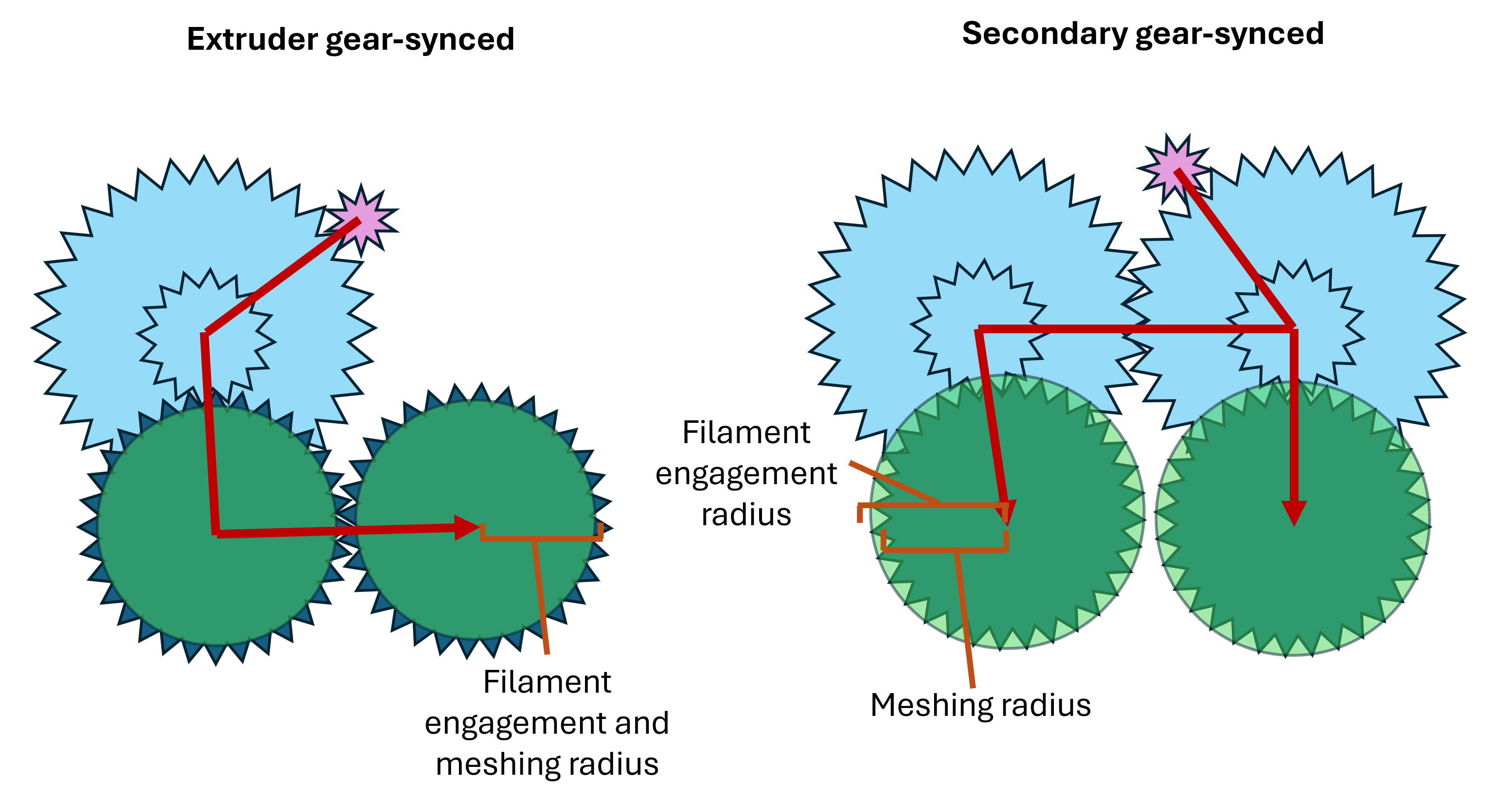
The reduction gearing used by filament path changers is worth remarking on. There are two main categories of drivetrain in these systems, and one minor one, each with its own design considerations. They are categorised here by how the two sides of the drivetrain are synced. Both of the major arrangements use multistage spur gear secondaries, in the manner of LGX gears.
Extruder gear-synced drivetrains
These are the closest to their LGX/HGX progenitors. The driven side is stationary and only the filament arm pivots, actuated by pressing sideways against the dock to dock or undock a tool. Because one side of the drivetrain does not move at all, some lateral movement of the filament is needed. As in a normal extruder, the tensioner arm pivot need not be coaxial with either gear.
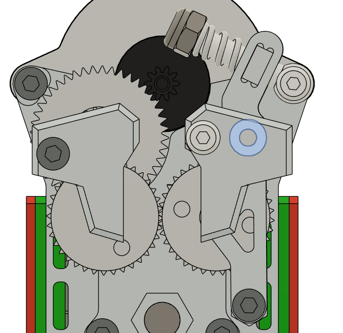
Systems of this type are essentially LGX or HGX extruders with an extended tensioner lever and a larger range of tensioner movement. Ordinary HGX/LGX extruder gears, those where meshing radius ≈ filament engagement radius, can therefore be used.
Secondary gear-synced drivetrains
These are closer to the dynamic extruder used in INDX. Both arms swing open and closed, the pivot for each is coaxial with its secondary gear, and the two arms are synced by the secondary gears rather than by the extruder gears.
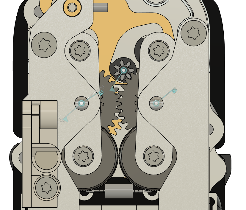
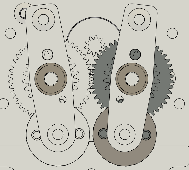
This is arguably the more elegant design, in that the arms swing cleanly open to let the filament clear during docking and undocking. There is a practical catch for anyone wanting to use it in a FOSS design, though.
The extruder gears here must have meshing diameter < filament engagement diameter, so that they mesh only with their secondaries and never with each other. Ordinary extruder gears do not: meshing radius ≈ filament engagement radius, so putting a pair of them in this arrangement closes the drivetrain into a loop, synced at both the secondaries and the extruder gears. In a fixed drivetrain that causes no great problem, but in a pivoting arm system the effective meshing diameter of the extruder gears varies with how far open the arms are, which can show up as chatter and extrusion artifacts.
Nothing on the market at the time of writing meets that requirement, which is why YUDX has as many custom gears as it does. That may not continue to be the case: several designs now use gears of this kind, so they are likely to become easier to source.
Tool-carriage synced drivetrains
This atypical type is used in the Oosaka and in the unnamed toolchanger designed by Matti. The motor axis may be rotated 90 degrees from its usual orientation so that it lies along X. Mechanically it resembles an extruder gear-synced drivetrain, but with the tensioner gear on the tool instead of the carriage. Such systems have to resist the tensioner trying to decouple the tool from the carriage, and in exchange they avoid needing a complex opening motion to accommodate the filament path.
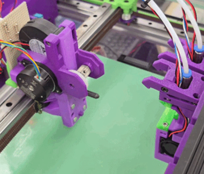
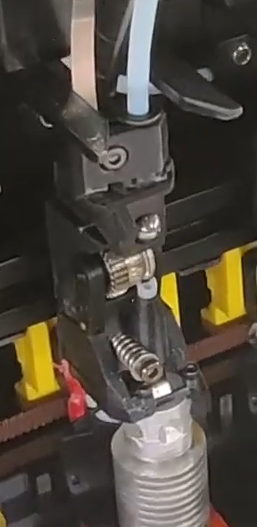
These may look like gear swapping toolchangers. They are not counted as such here, because the tool-carriage interface is still the filament path, as it is in the wired, pogo/inductive and hotend fan swapping types. Gear swapping extruders such as the Flashforge Creator 5 do not split along the filament path at all; they split between the extruder gears and the motor. Tool-carriage synced drivetrains therefore face problems closer to those of the wired filament path changers, an extruder applying a decoupling force to the tool, than to those of the gear swapping type, which are custom gears and meshing during docking and undocking.